Theory
Ohm’s Law states that the current flowing through a conductor is directly proportional to the voltage across its ends, given that temperature remains constant. It is represented by the equation:
$$ \begin{equation}\begin{aligned} V=IR\\ \end{aligned}\end{equation} $$This means that resistance is simply the ratio of the voltage applied to the current flowing through the resistor/conductor:
$$R=\frac{V}{I}$$
Thus we can determine the resistance of a device in a circuit by varying the voltage applied to it and measuring the corresponding current.
Aim
To determine the electrical resistance of a passive device in a circuit by using Ohm’s Law
Materials/Apparatus
- Rheostat
- Voltmeter
- Ammeter
Diagram
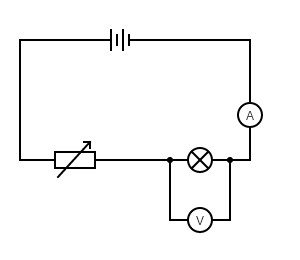
Method
- Set up the circuit as depicted in the diagram above
- Set the voltage of the student’s power supply to 6 volts
- Adjust the rheostat to a random position
- Measure and record the voltage across and current through the bulb
- Repeat steps 3 and 4 for a total of 5 sets of readings
Results
| Voltage | Current | Resistance |
|---|---|---|
Data Analysis
- Find the resistance for each voltage-current pair in the table above
- Plot a graph of voltage versus current
- Calculate the gradient of the best fit line
- From the gradient, determine the resistance of the bulb